Amir Massah B.a, Arman Sharifi K.a,b, Yaser Salehiniaa, Farid Najafia*
*Faculty of Mechanical Engineering, K.N.Toosi University of Technology, Tehran, Iran *School of Mechanical Engineering, Sharif University of Technology, Tehran, Iran
*Corresponding author. Tel.: +989352573394; E-mail address: amir.massah@gmail.com
Abstract: Dynamic gait planning for humanoid robots encounters difficulties such as stability, speed, and smoothness. In most of previous studies, joints’ trajectories are calculated in 3D Cartesian space, then, introducing boundary conditions and using polynomials, the first and second derivatives of the motion are ensured to be continuous.
Then, the stability of the motion is guaranteed using Zero Moment Point (ZMP) stability criterion. In this study, a trajectory planner is presented using the semi-ellipse equations of the motion; the continuity of the derivatives is preserved. Stabilization of motion is attained through using ZMP criterion and 3d inverted pendulum equations in three slope conditions. The effectiveness of the proposed approach is investigated using Webots software.
Implementing proposed approach, smoothness, stability, and convenient speed (rather than 17 cm/s in flat condition) are achieved.
Keywords: Trajectory Planning, Humanoid Robot, ZMP, NAO;
1. Introduction
Exciting challenge of the locomotion of the humanoid robots attracts many researchers [1]. Nonetheless, because of dynamical complexity, passive degree of freedom, changeability of kinematic structure, and repeatability of motion, humanoid robot locomotion is far from human locomotion.
The well-known approach of Vukobratovic [2], called Zero Moment Point (ZMP), is one of the earliest and finest approaches to encounter the problem of biped robot locomotion. This approach was derived from the dynamical analysis of robot motion viewpoint. The term of ZMP refers to a point on the ground where the resultant moment caused by robot gravity and robot body inertia is vanishing [3].
This approach guarantees the dynamical balance of biped robot while the ZMP is located in the polygon that is formed by the feet on the ground, called support polygon [3,4]. The first ZMP-based 12-DOF biped robot, driven by hydraulic actuators, is developed by [1]. The linear inverted pendulum mode (LIPM) is introduced in [5] to calculate the COG trajectory analytically.
In this method, the LIPM is used to generate the COG trajectory for a single support phase. Incorporating the ZMP based and the LIPM techniques, a novel walking pattern generation with arbitrary foot placements is proposed in [6]. Using the preview control approach of the ZMP, the exact multi body dynamics were calculated based on simple inverted pendulum method.
The motion control of biped robots is investigated in [7]. Describing gait synthesis of biped locomotion as an optimization problem with the constraint, [7] proposed a dynamically stable gait planning in slope surface. Furthermore, based on dynamic walking algorithm in [8], a several online controllers were used to deal with uneven and inclined ground by [9]. The concept of the ZMP is implemented on various famous robots as NAO provided by French company Aldebaran Robotics. Kulk and Welsh [10]
improved the speed, robustness, and efficiency through allowing the robot to settle into more natural gate by means of modifying the low-level positional controller. Using a simple inverted pendulum model, an implementation of omni- directional walking is proposed in [11] in which a preview controller is applied to generate dynamically balanced center of mass trajectories. Incorporating a feedback controller with an online generated feet pattern to assure an stable gait, Czarnetzki, et al. [12] proposed a novel observer-based control system to achieve reactive motion generation for dynamic biped walking. Graf, et al. [13] present a COM-based closed- loop gait for the NAO robot, the torso pose of the robot is the underlying idea of the active balancing used in their approach.
In this paper, a trajectory planning approach is proposed for NAO humanoid robot based on ZMP criterion using cart- table model. The performance of the proposed approach is investigated in different slope conditions using Webots simulation environment.
2. Methodology
2.1 Robot Model
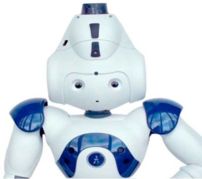
Robot and its surrounding environment are simulated in Webots software which is able to simulate robots with industrial qualities in dynamical and physical aspect of view [14]. NAO is an autonomous, programmable and medium sized humanoid robot [15] that is developed by a French company, Aldebaran Robotics, in 2004 (as shown in Fig. 1). Sony’s dog robot AIBO has been replaced by NAO in the RoboCup Standard Platform League (SPL) since 2008. The NAO RoboCup edition has 21 DOFs while the academic edition of it possesses 25 DOFs. The height and the weight of NAO are 58cm and 4.3kg, respectively.
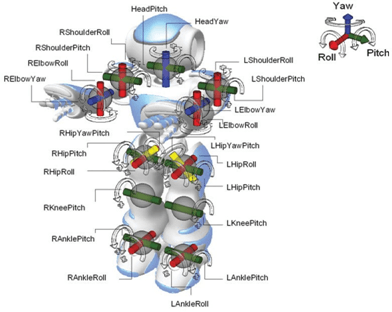
Fig. 1. NAO robot kinematic structure.
2.2 Gait Planning
Humanoid robot movement control is initiated with generating the joints’ trajectories. The trajectory delivers the corresponding desired position at each instant time; therefore, it commonly stated as a parametric time function. For determining this function, other implementation issues, such as time discretization, time derivatives, etc., should be considered. Trajectory planning of humanoid robots could be executed in joint space (directly designating the joint angles time evolution) or Cartesian space (designating the end effector position and orientation). The former planning procedure contributes the fast and simple solution by means of avoiding inverse kinematics problem in which indirect control of the end effector pose results in difficult collision avoiding.
While in Cartesian space planning, external environment geometric constraints could be met more directly although inverse kinematics problem must be solved. In order to generate trajectories in Cartesian space, two stability criteria exist: static stability and dynamic stability. In static stability, neglecting the robot dynamics, the center of gravity (CoG) is considered as stability criterion.
This assumption leads to restrict the applicability of this approach for slow motions of the robots. Consequently, most researchers applied dynamic stability in their studies. Center of pressure (CoP), Zero Moment Point (ZMP) [16], and Foot Rotator Indicator (FRI) [17] are the most common dynamic criteria. The ZMP criterion is adapted to synthesis humanoid gait. ZMP is calculated by Eq. 1 and Eq. 2. The underlying idea of the ZMP criterion states that while the ZMP is located in support polygon, the dynamically balanced walking of humanoid robot is guaranteed.
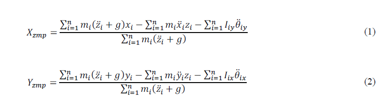
Xzmp and Yzmp are x and y coordinates of ZMP, respectively. zi, z̈i, xi, ẍi, yi, and ÿi are the position and the acceleration of the robot’s parts along the z, x, and y coordinates, respectively. Also, mi is the mass of the robot’s parts. Iix and Iiy are the inertial components of the robot’s parts around x and y coordinates, respectively. θ̈ ix and θ̈ iy are the rotational acceleration of the robot’s parts around x and y coordinates, respectively. Finally, g is the gravitational acceleration.
Unlike the original work in [2] where the recommended ZMP pattern is realized by a model with a compensating mechanism, the recommended ZMP trajectories has been realized by a body motion in the recent implementations. Furthermore, the foot trajectories are prescribed instead of leg joints trajectories. The leg joints motions are determined using foot trajectories and inverse kinematics of the robot. So, being ZMP a function of joint’s position, velocity, and acceleration results in determining the feasible joint positions which satisfies the prescribed reference ZMP in the ZMP based walking trajectory generation. The prescribed reference ZMP will be satisfied by the support foot motion whereas the swing foot motion will be designed independently from the ZMP equations in the Cartesian space.
Support leg and swing leg are considered as two manipulators in the gait generation. Consequently, the humanoid gait generation could be viewed as manipulator trajectory generation. In walking phases (double support and single support), the hip is the base frame and the ankle is the end effector for each foot. The ankles’ motion in base frames is based on semi- ellipse equations as Eq. 3.
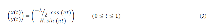
Fig. 2 depicts swing and support states of legs in base frames, respectively. The double support phase of the walking cycle is crucial due to its effect on increasing the stability of walking and reducing the impact between the swing leg and the ground although it is only about 20 percent of walking cycle [18]. If SST and DST denote the single support time and the double support time, then, the total time of a gait cycle (TT) is as Eq. 4.

Regards to the gait cycle timing, the semi-ellipse equations, and the parameters defined in Fig. 2, the swing and the support ankle motion paths on flat and slope (by any gradient angle θ) are calculated. The swing ankle path of both feet in x- direction and y-direction are obtained by Eq. 5 to Eq. 8.
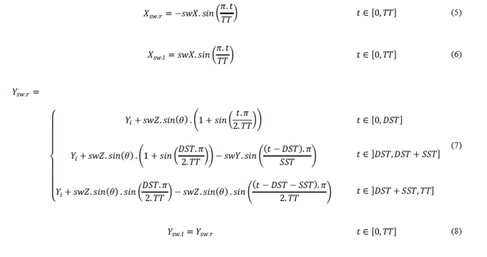
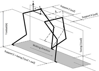
Fig. 2. Swing and support legs’ states in a step. Conditions a, b, and c, illustrate three states of double support, middle of single support, and double support phases.
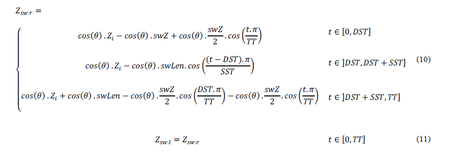
A new variable, swLen, is considered as Eq. 9.

Now, z-coordinate of the swing ankles are acquired by Eq. 10 and Eq. 11.
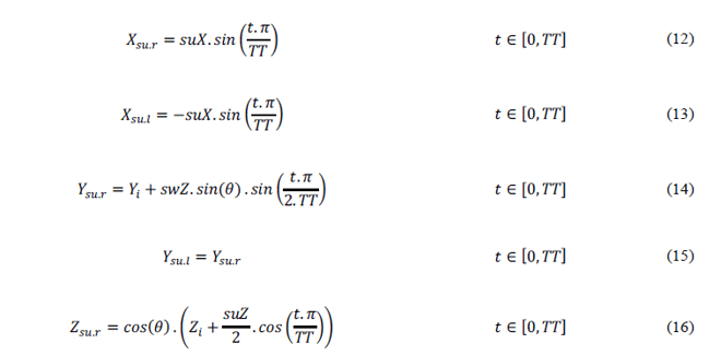
The path of support ankles in all directions is achieved by Eq. 12 to Eq. 16.
The gradient angle (θ) is determined by Eq. 17.

The trajectories must have 1st-order and 2nd-order derivative continuities. The 1st-order derivative continuity implies the joint smooth velocity, while the 2nd-order derivative continuity guarantees the joint smooth acceleration or torque. Besides, it can be proved that the 1th-order and 2nd-order derivative continuities in Cartesian space can guarantee the 1th-order and 2nd-order derivative continuities in joint space and vice versa, because the transformation from one space to another is a one- to-one mapping. In other words, any trajectory generation in Cartesian space has to convert to joint space to control each joint.
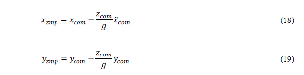
Because of considering overall dynamics of the robot, Vukobratovic proposed ZMP equations suffer from complexity and intensive computations [17]. Kajita simplified the ZMP equations by introducing a cart-table model based on the ZMP and the inverted pendulum approach [7].
The 2-D cart-table model is illustrated in Fig. 3. As shown in Fig. 3, the robot is assumed to be a point mass, and the center of mass (COM) height is considered to be constant in the forward movement of the robot. The dynamic equations of this model are as Eq. 18 and Eq. 19.
Moreover, by dynamical analyzing of the 3-D linear inverted pendulum model, Kajita decoupled its equations into two 2- D linear inverted pendulum models for 3-D cart-table model.
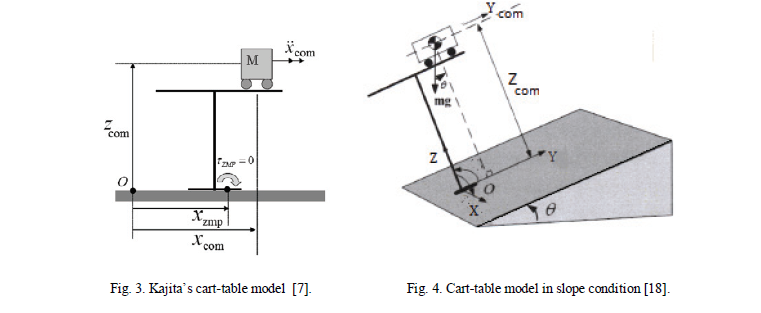
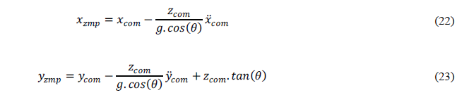
In case of flat terrain, the 3-D model has been simplified into two separated 2-D models, whereas in case of slope terrain, the variable height of COM causes difficulties in decoupling the frontal and sagittal motion. In [19], a new frame is attached to the slope and assumed that the slope has constant height (as shown in Fig. 4). Obviously, the COM is translating in parallel manner with respect to the slope. Therefore, by introducing a new frame, the frontal and sagittal motion can be decoupled. For upward slope walking, the ZMP equations are as Eq. 20 and Eq. 21.
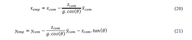
And downward slope walking equations are as Eq. 22 and Eq. 23.
3. Discussion and Simulation Results
In this section, the results of the proposed trajectory planner are discussed through simulations on NAO robot using Webots robotics simulator. The Webots simulator is based on ODE (open dynamic engine), an open source physics engine
for simulating 3-D rigid body dynamics [20]. The simulations are executed on a 2.4 GHz core Duo 2 machine with the 3 GB of physical memory and 3 MB of cache memory.
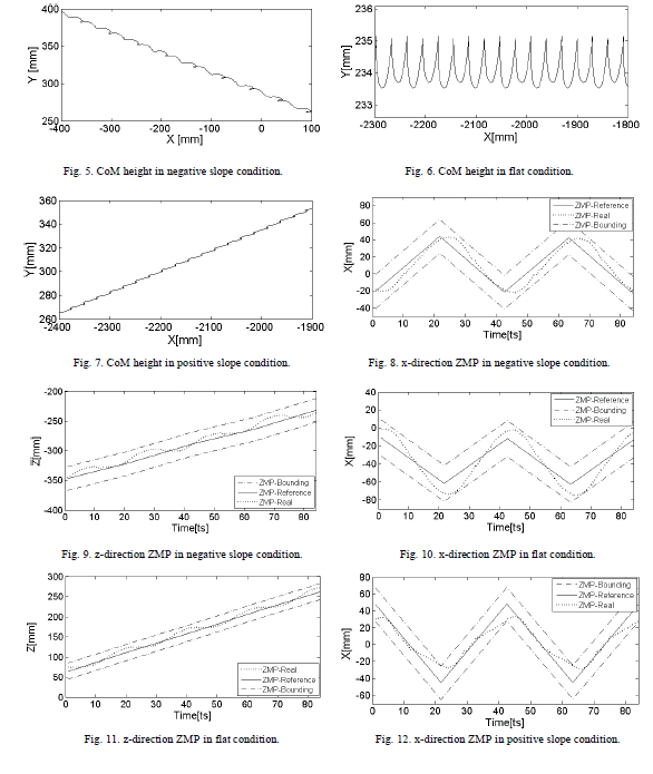
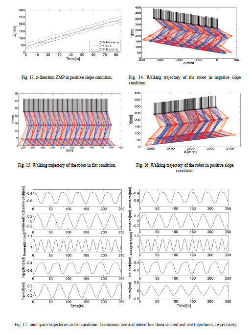
Fig. 5-7 depict the CoM height of the robot in negative slope (-15ο), flat, and positive slope (+10ο) conditions, respectively. Fig. 8-13 illustrate the ZMP path of the robot in these three conditions. Fig. 14-16 and Fig. 17 represent the walking trajectories and joint space trajectories in these three conditions, respectively.
Now, the maximum attained speed of this study and several other references are reported. Implementing proposed approach on NAO robot in Webots simulation environment, the maximum speed of 17 cm/s is achieved. In [10], applying their approach on real NAO robot, the maximum speed of 14 cm/s is obtained. The maximum speed of 20 cm/s is attained in
[12] using SimRobot simulation of NAO robot. Furthermore, [11] and [14] succeeded to achieve the maximum speed of 10 cm/s and 12 cm/s, respectively. All these speeds are recorded in flat surface and forward direction condition.
4. Conclusions
In this paper, a trajectory planner proposed to attain a dynamic walking for NAO humanoid robot in three slope conditions. Initially, ankle joint paths (in other words, equations of motion) are fully developed in all three conditions. Swing and support legs are considered two manipulators. Also, the path of each ankle is based on a semi-ellipse equation in the bases frames. The continuity of the first and second derivatives of motion is ensured by means of semi-ellipse path choice. Finally, using ZMP stability criterion and 3D inverted pendulum model, the generated paths are stabilized. The performance of the proposed approach is evaluated through simulation in Webots software. Results indicate that the desirable properties of dynamic stability, smooth motion, and satisfying speed are achieved in all three conditions.
Reference
- Takanishi A, Ishida M, Yamazaki Y, Kato I. The realization of dynamic walking by the biped walking robot WL-10RD. Int. Conf. Adv. Robot. (ICAR’85); 1985, p. 459–66.
- Vukobratovic M, Stepanenko J. On the stability of anthropomorphic systems. J Mathematical Bioscience 1972;15:1-37.
- Vukobratovic M, Borovac B. Zero-moment point - thirty-five years of its life. Int. Humanoid Robotics 2004;1(1):157-73.
- Vukobratovic M, Frank AA, Juricic On the stability of biped locomotion. IEEE Trans. Biomedical Engineering 1970;17(1): 25-36.
- Kajita S, Kanehiro F, Kaneko K, Yokoi K, Hirukawa H. The 3D linear inverted pendulum mode: A simple modeling for a biped walking pattern generation. In IEEE Int. Conf. Inteligent. Robots and Systems; 2001, p. 239–46.
- Kajita S, Kanehiro F, Kaneko K, Fujiwara K, Harada K, Yokoi K, Hirukawa H. Biped walking pattern generation by using preview control of zero- moment point. In IEEE Int. Conf. Robotics and Automation; 2003, p. 1620–6.
- Zhou C, Yue PK, Ni J, Chan Dynamically stable gait planning for a humanoid robot to climb sloping surface. In Proc. IEEE Int. Conf. Robotics, Automation and Mechatronics; 2004, p. 341–46.
- Kim JY, Park IW, Oh J Experimental realization of dynamic walking of the biped humanoid robot KHR-2 using zero moment point feedback and inertial measurement. J Advanced Robotics 2006;20(6):707-36.
- Kim JY, Park IW, Oh JH. Walking control algorithm of biped humanoid robot on uneven and inclined floor. J. Intelligent and Robotic Systems 2007;48(4):457–84.
- Kulk JA, Welsh JS. A low power walk for the NAO robot. In Proceedings of the Australasian Conference on Robotics & Automation;
- Strom J, Slavov G, Chown E. Omnidirectional walking using ZMP and preview control for the nao humanoid robot. In RoboCup Conference;
- Czarnetzki S, Kerner S, Urbann Observer-based dynamic walking control for biped robots. J Robotics and Autonomous Systems 2009;57(8):839– 45.
- Graf C, Hrtl A, Rfer T, Laue T. A Robust Closed-Loop Gait for the Standard Platform League Humanoid. In RoboCup Conference;
- Michel WebotsTM: Professional Mobile Robot Simulation. Int. J. Advanced Robotic Systems 2004;1(1):39-42.
- Gouaillier D, Hugel V, Blazevic P, Kilner C, Monceaux J, Lafourcade P, Marnier B, Serre J, Maisonnier B. Mechatronic design of NAO humanoid. In IEEE Int. Conf. Robotics and Automation (ICRA), Kobe, Japan; 2009, p. 769-74.
- Shih CL, Gruver WA. Control of a biped robot in the double support phase. IEEE Trans. System, Man, and Cybernetic 1992;22(4):729-35.
- Goswami Postural stability of biped robots and the foot-rotation indicator point. Int. J. Robotics Research, 1999;18(6):523-33.
- Huang Q, Yokoi K, Kajita S, Kaneko K, Arai H, Koyachi N. Planning walking patterns for a biped robot. IEEE Trans. Robotics and Automation 2001;17 (3): 280-9.
- Huang W, Chew CM, Zheng Y, Hong GS. Pattern Generation for Bipedal Walking on Slopes and Stairs. In Proc. IEEE/RAS Int. Conf. Humanoid Robots; 2008, p. 205-10. Open dynamic engine documentation [online], http://www.ode.org.
© 2012 The Authors. Published by Elsevier Ltd. Selection and/or peer-review under responsibility of the Centre of Humanoid Robots and Bio-Sensor (HuRoBs), Faculty of Mechanical Engineering, Universiti Teknologi MARA. Open access under CC BY-NC-ND license.
Ready to get started with your robot? click below to get get a free estimate, without any commitment"


 Too much to read? Don't have time?

.webp?width=124&height=124&name=image%20(1).webp)
.webp?width=169&height=87&name=image%20(2).webp)