
Arkadiusz Gardecki ∗ Michal Podpora ∗ Aleksandra Kawala-Janik ∗
∗ Opole University of Technology – Faculty of Electrical Engineering, Automatic Control and Informatics UL.Proszkowska 76, 45-758 Opole, Poland (e-mail: a.gardecki@po.opole.pl, m.podpora@po.opole.pl, kawala84@gmail.com).
Abstract: The paper describes an algorithm for supporting the control of the humanoid robot NAO, using an external system, equipped with a laser scanner. The use of an external 2D laser scanner clearly increases the reliability of robot movements in a closed area. The proposed algorithm is implemented and tested in an external system that supervises the navigation of the NAO robot. It combines information from built-in robot sensors with the additional computational capabilities of an external control system, as well as the laser scanner data. The proposed system enables the possibility of fast and convenient localisation and navigation of one or more robots in a close environment.
© 2018, IFAC (International Federation of Automatic Control) Hosting by Elsevier Ltd. All rights reserved.
Keywords: collision avoidance, humanoid robots, laser radar, robot control.
1. INTRODUCTION
NAO robot (see: Gouaillier et al. (2009)) is an au- tonomous, mobile, humanoid robot designed by the French company Aldebaran Robotics, acquired by SoftBank Robotics. A significant advantage over other humanoid robotic platforms is its full programmable by using dedi- cated OS system NAOqi Softbank NAOqi Developer guide (2017) and development environment Choregraphe Pot et al. (2009).
Human-Machine Interaction with the robot may take place in many ways – by using touch sensors, by vision input image analysis or by speech recognition. The robot also has many sensors useful during movement (Fig. 1), i.a.:
- limit switches (bumpers) on the front part of the feet,
- two switchable cameras with partially overlapping coverage – image from the camera can be used either as a starting point for own
- image processing algorithms or it can be processed using predefined built-in modules,
- two ultrasonic sensors which allow it to estimate the distance to obstacles in its environment
For acquisition of the robot’s surrounding data can be per- formed using sensors already included in the platform (Fig. 1): ultrasonic sensors, bumpers, vision system or data from gyroscopic sensors. In this paper authors propose using an additional external device – a LIDAR laser scanner, able to visualise the spatial boundaries of the robot’s environment. The paper also introduces an algorithm for processing the readings from LIDAR and integrating the acquired knowledge with the robot’s sensors, which is being executed in an external server, building up a common decision to be passed to the robot’s control system.
The use of an external server addresses the problem of limited computational resources of a robot platform. The integrated out-of-the- box sensors do not offer a feedback that would be precise enough for robust and secure autonomous navigation in a non-empty room, especially if the key issue is to get to a precise location, not just to wander around. The proposed algorithm is tend to take the simplest possible means to significantly increase the navigational capability of the NAO robot. Of course, the idea and the algorithm can be applied to any other humanoid/mobile robot.
2. SAFE REGION IDENTIFICATION AND COLLISION AVOIDANCE ALGORITHM
The algorithm, presented in this paper, is designed to accomplish two basic goals: A) to define secure area in which the robot can perform unrestricted actions and movements (because there are no obstacles, walls or humans), and B) to determine the actual location of the robot within the environment and to track its movement (even if the robot is not in the LIDAR’s field-of-view at a time).
In case of a humanoid (walking) robot, the knowledge about the robot’s physical environment becomes especially valuable, while it’s important to know the shape and area in which there are no obstacles. The robot is able to move with increased velocity and perform more vivid actions/ movements. If the robot enters an area of increased probability of encountering obstacles/humans, the movements should be performed in more cautious (safe) way – by modifying the movement algorithm and strategy. Walking into an obstacle often results in robot falling down, and walking into a human would be dangerous not only for the robot. The NAO robot contains numerous sensors, included for acquiring information about the robot’s environment. How- ever, these sensors have significant limitations:
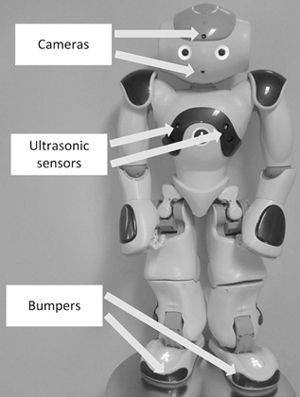
Fig. 1. NAO humanoid robot and some of its sensors that can be used during movement.
the ultrasonic sensors detect an obstacle without giving any information about its size or shape, the vision system identifies only simple (or: of limited variety) objects (the built-in vision processing system is rather sensitive to lighting conditions, it has long response time, limited efficiency, and it is time- and CPU-power-consuming; the limitations of the out-of-the-box vision subsystem are mainly the result of the limitations of the hardware and its processing power, and using an external computational resource for running advanced scene analysis and feature extraction algorithms would improve the quality of outcomes – the authors do not cover this broad issue in this paper). The bumpers, located in the feet of NAO robot, should be the last resort in avoiding a collision, while they trigger an event too late - when the collision has already occurred – although the collision would eventually be detected, the system would not have the time to prevent its consequences.
These limitations can be surpassed by using a laser scanner. In the past it was possible to purchase a special version of head for the NAO humanoid robot SoftBank Robotics (2017), equipped with a laser scanner (Fig. 2). It was a convenient way for researchers and students to start developing SLAM (Simultaneous Localisation and Map- ping) algorithms (the laser head included Gomez (2017) Hokuyo Laser Range Finder – URG-04LX). The relatively easy hardware replacement as well as the pre-programmed ready-to-use ALLaser libraries were strong advantage of this solution, whereas the cost and no protection against damage resulting from a fall were the main disadvantages.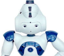
Fig. 2. NAO Laser head unit Gomez (2017).
Currently, the laser head is not available for sale. The Pepper robot Gardecki et al. (2017), the successor of NAO robot, also produced by SoftBank Robotics, is equipped as standard with laser scanners, significantly increasing its capabilities of acquiring knowledge about its environment. In this paper the authors have chosen to implement an external device with a rotary laser unit. This choice has been made keeping in mind the following two aspects: 1) no need for hardware modifications of NAO robot, and 2) an easy option to adjust the location of the sensor in relation to the location of the objects in the room.
2.1 Safe Region Identification Algorithm
In order to determine the areas of safe and limited robot movement, the following algorithm was proposed using data from Lidar:
1) Initialization/setup stage:
- Load initial scene state from LIDAR (Fig. 3);
- An expert marks permanent obstacles (Fig. 4);
- The robot moves while observing LIDAR data, marks its location (Fig. 5);
2) Runtime loop:
Reload scene from LIDAR;
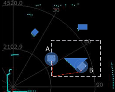
- Check and redefine the areas for safe movement (Fig. 6 – A);
- Check if the planned movement enters the area of limited movement safety (Fig. 6 – B);
- Perform action, inform the system about changing the location.
The scene analysis is performed by applying image processing algorithms to the prepossessed LIDAR data. The following figures illustrate the various stages of the algorithm’s operation (especially Fig. 6).
Marking permanent obstacles, depicted in Fig. 4, is per- formed only once for a new room setup. Its purpose is to verify the knowledge (obstacle boundaries) acquired by the LIDAR, and to define which boundaries are permanent. It will be helpful in defining primary (safe) and secondary (unsure) movement security zones.
Next step is to connect two initially separate knowledge domains: data from the laser scanner and the data from the robot’s odometry methods. Usually the LIDAR-based approach is replacing other methods, while it is considered to be more accurate and more developed, however using LIDAR data as complementary source of information is also popular. In our case – when the laser scanner is an external device (mounted in the room not on the mobile platform) – it should be treated as an additional source of information.
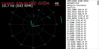 Fig. 3. Initial data acquired from LIDAR – left: Screenshot of the default RpLidar output preview, right: raw data output.
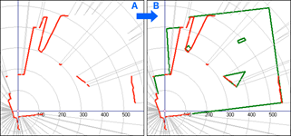
Fig. 4. Permanent obstacles on the stage marked by an expert.
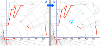
Fig. 5. The robot connects to the system and marks its location and orientation.
external system to (1) get the ”map” of the area, to (2) post their location (or modify their location information in the system) or to (3) negotiate their position in the ”map”. The result of the negotiation procedure is the synchronization of the system’s LIDAR ”map” and the robot’s perception of its position. The negotiation procedure is introduced in more detail in the next subsection.
After the negotiation stage, when the robot is ”aware” of its position within the map, two types of areas can be delineated: (1) safe – the area is clearly visible to the LIDAR device, the robot is near (within) this area, all walls, obstacles, furniture, etc. are treated with a margin of safety, all moving objects are treated with double margin of safety (this zone is shown in Fig. 6 – A), and (2) limited movement safety zone – the area that is not visible to LIDAR, although the layout of walls and permanent obstacles, marked by an expert, suggests that this area can be used by a robot for navigation purposes (this zone is visualized in Fig. 6 – B)
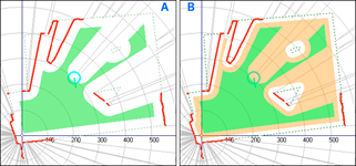
Fig. 6. Safe – (A: green/gray) and Limited – (B: or- ange/light gray) movement regions are defined.
The usage of the knowledge of these two zones is presented in the next chapters.
2.2 Approximation of the Robot’s Position Algorithm
Inferring the robot’s location from the LIDAR data implies the quality and precision of robot’s location. Depending on the distance between laser scanner device and other elements of the scene (including the robot), the quality of information can significantly vary. For this reason it is crucial to know the exact location of the robot within the LIDAR-generated scene (map).
The ”location negotiation” algorithm is usually executed only once, in the initialization/setup stage. After connect- ing to the external system and downloading two LIDAR data frames/requests, the robot’s algorithm compares the frames to check if there is are any moving objects. Than, if the robot’s ultrasonic sensors report some free space in front of the robot, it performs a short-distance move. During the movement the LIDAR data is being analyzed for changes, and when the robot stops, this should also be noticeable in the data. The robot reports its own location to the system, so that it would warn other robots of its presence. The robot stores/refreshes its own location in its memory and in non-volatile memory/storage. It is theoretically possible to mark the locations of charger units, although the use case presented in chapter III did not include this issue. After the ”location negotiation” stage the physical movement of the robot can result in visible changes in LIDAR data, although it is possible to see (other) moving objects, which will not be confused (any more) with the robot’s own motion.
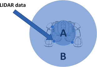
In the ”map” preview, the location of the robot is marked by a circle with a diameter of 24 pixels (it means region A diameter of 0.19 m and region B diameter of 0.5 m) – this circle includes a circumference of the robots physical construction (Fig. 7) as well as additional 0.155 m safety zone, which is a kind of correction for robot positioning errors. This 0.155 m margin is particularly useful during rotation of a humanoid robot.
|
Fig. 7. Robot localisation and zones based on its size and position. A – area approximating the size of the robot, B – additional safety zone. |
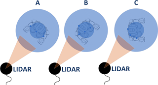
Fig. 8. Robot positions during accuracy tests regarding the location of LIDAR. |
The proposed robot positioning algorithm is based mainly on LIDAR data. The readings which are (or at least should be) identified as the robot’s position, usually form a circle.
In the proposed algorithm, the extreme readings (Fig. 7 – upper left and bottom right) always lie on a circle.
If there are more robots in the scene, their locations (Fig. 5 – B) and safety zones (Fig. 7) will additionally affect the shape (Fig. 5) of the safe-movement-area and the limited- movement-area.
The results of determining the robot’s position (based on the proposed algorithm in comparison to the actual robot location) are summarized in Table 1 below. These errors seem to be acceptable, given the ambiguity of recovered robot’s position based on the LIDAR data (Fig. 8).
Table 1. The Accuracy of Robot Localisation Based on LIDAR data Depending on Ropot Position (Error Absolute Value)
|
Distance from LIDAR |
Error – A |
Error – B |
Error – C |
|
1000 mm |
18 mm |
5 mm |
19 mm |
|
1500 mm |
17 mm |
10 mm |
11 mm |
|
2000 mm |
18 mm |
4 mm |
13 mm |
|
2500 mm |
13 mm |
14 mm |
16 mm |
|
3000 mm |
21 mm |
18 mm |
24 mm |
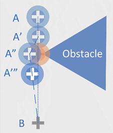 Fig. 9. Example of collision avoidance algorithm operations A – starting robot position, A’, A”, A”’ – next robot positions where recalculated target trajectory, B – robot target position.
2.3 Collision Avoidance Algorithm
If the robot’s navigation from point A to point B can be performed without leaving the safe-movement-area, it is performed with normal (or increased) velocity, the robot can use the area to set an optimal route (energy-efficient or time-efficient or optimal for whatever criterion). If the robot has to navigate outside the safe-movement-area, the movement is performed with increased precautions, decreased speed, and giving highest priority and refresh rate to its ultrasonic sensors.
If the robot’s sensors report an obstacle that precludes performing the planned movement/navigation task, the route is being recalculated including new limitations (Fig. 9). All moving objects (including humans) are treated with double safety zone.
3. USE CASE FOR PRACTICAL IMPLEMENTATION
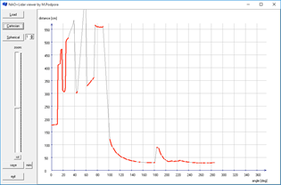
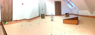
The algorithm presented in this paper has been tested in laboratory conditions, using NAO robot, Slamtec RPLI- DAR Slamtec – RPLIDAR A2 (2017), and some obstacles, in the following use case. The robot was placed in a random location inside the lab, the LIDAR device was placed in the corner of the laboratory, and three obstacles were placed on the floor (Fig. 12; green shapes within the room depicted in Fig. 4 – B). The LIDAR device was connected to a PC with software to refresh the LIDAR data. The data (view-able as shown in Fig. 3 – left) can be imported as a series of measurements (Fig. 3 – right) into any custom application.
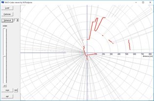
Working with LIDAR data requires loading the series of measurements (depicted in relatively difficult-to-read image in Fig. 10) and recalculating the data into spherical 2-dimensional coordinate system (Fig. 11). The code and experience gained during the implementation of the viewer presented in Fig. 10 and 11 can be directly re-used in implementation of the final system interfacing the external LIDAR with robots navigating within the area.
|
Fig. 10. Screenshot of the LIDAR data preview applica- tion; Cartesian preview of raw data. |
Fig. 11. Screenshot of the LIDAR data preview applica- tion; spherical preview of raw data. |
The next tool that should be implemented is the graphical tool for setting up the area parameters – its boundaries and permanent obstacles (Fig. 4). This task is an important stage of the setup, while it supplements the LIDAR data (which is often far from being perfect) and by validating the boundaries of the robot’s working area makes it trust- worthy. The resulting room description (”map”) is still not perfect – e.g. Fig. 12 shows thick red/gray lines in top left part of the image, which mean that the implemented algorithm, for some reason, treats these lines as an actual boundary.
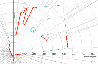
Fig. 12. The LIDAR data on top of predefined room boundaries and predefined obstacles (dashed lines), with robot localisation and orientation (circle) nego- tiated from NAO robot.
This can also be seen in Fig. 6, in which the area behind the top left obstacle (which is just a cardboard box – Fig. 14) has been excluded from all the available movement area categories and is considered not to be accessible. This is obviously a mistake, which is present in this particular data frame. Another mistake visible in Fig. 12 is that the top right obstacle in this particular data frame appears to be invisible for the laser scanner. Both of these mistakes did influence the safe- and limited- movement areas (Fig. 6), but only for this particular data frame. To deal with such issues, a simple solution has been proposed – a short-term memory, remembering 5 last data frames to minimize the influence of massive changes in the areas. Subtle changes and changes that do not modify the accessible area in a radical way can mean a moving object, and such changes are taken only from the last frame.
accessible area in a radical way can mean a moving object, and such changes are taken only from the last frame.
When the system is ready, it can accept incoming connection requests from robots, send current data frame, and accept robot’s current location/position information. One of the possible data formats for convenient data trans- mission is the JSON format, although any other format would be acceptable. In the exemplary case, the NAO robot connects to the server (by connecting to a static IP address), and using a Python script gets the JSON data of the most recent frame from the server. Performs a short-range move (if possible) to observe the movement in changes of LIDAR data – to calibrate its location within the LIDAR ”map”. This ”location negotiation” algorithm was introduced in one of previous chapters. The robot’s location is sent to the server so that it would be able to include it in the JSON structure in case more robot’s would connect to the server and navigate within the same area. In the preview, the position of the robot is visualized as a circle with a diameter of 24 pixels, while in the server’s broker module the position of a robot is presented as a center of circle and as a change in the shapes of the safe- and limited- movement areas. The circle (in the preview), as well as the subtracted part of the limited-movement- area (in the ”areas” data) is approximately the same size as the outer boundaries of the robot’s construction in a standing position (Fig. 7 and 11).
The robot is able to get the information from the server in one of the following forms (structures):
- Raw LIDAR data
- LIDAR data + permanent walls and obstacles
- LIDAR data + permanent walls and obstacles +locations of the robot(s),
- Primary zone (safe-movement-area) data,
- Secondary zone (limited-movement-area) data
In the use case’s practical implementation the route planning was not implemented in the external system, however it would be a good idea to do so, because it would enable the possibility to synchronize the routes of many robots in such a way that they would not collide with each other. Implementing the route planning on the robot results in a possibility to encounter other robots on its path, which would need special handling.
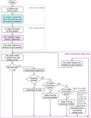
Fig. 13. A sketch of the general algorithm.
Nonetheless, the robot’s route synchronized with LIDAR ”map” data or with the system’s ”areas” data is not providing the ultimate navigation solution, while there are areas not fully covered by the LIDAR, and there are areas of increased precaution, so there is no such possibility to ignore the robot’s sensors. For this reason, the robot’s odometry system is always an important part of the decision-making and safety algorithms.
4. MODULAR MOVEMENT CONTROL SYSTEM
In this chapter, the robot control algorithm is presented, which is designed as a modular implementation. The designed system is intended to offer the possibility of easy parameterization of data in modules, which helps tuning the algorithm to the layout of the room in which the robot is to move (inter alia: room dimensions – LIDAR range, LIDAR mounting height – robot’s cross section size, etc.). The modularity of the proposed system design is also helpful in testing alternative methods that accomplish particular tasks (e.g. various collision detection methods, strategies for determining a new movement trajectory, etc.).
5. RESEARCH EXAMINATION
In order to evaluate the efficiency of the proposed algorithm, the below mentioned tests were conducted. Their goal was to show if the use of the proposed system would significantly improve the precision in moving robot to a location or not (Fig. 14 and 15).
|
Fig. 14. The laboratory test setup for validating the algorithm (180-degrees panoramic photo).
|
Fig. 15. The obstacles, the robot and its movement trajectories visualized on top of the LIDAR preview. A robot starting position, B – robot position after collision with obstacle (robot has rotated during the collision), the dashed white line – planned trajectory, the dotted red line – robot’s trajectory using only built-in odometry algorithms.
|
significantly improve the precision in moving robot to a location or not (Fig. 14 and 15).
The path tracking accuracy of NAO robot is poor (e.g. Wen et al. (2014) and Wei et al. (2014)). The errors of reaching a given location even at a distance of 1 m can be significant. The reason for them is the composition of several factors: varying friction and unevenness of the floor surface, asymmetric movements of the left and right legs of the robot during walking, angular precision error when rotating the robot, looseness of the robot’s construction, etc. The severity of these issues may be analyzed and evaluated individually, but in general they can can also be treated as random. An example of problems with completing a test route using only the built-in odometry mechanisms is presented in Fig. 15.
As a result of navigation using only the built-in odometry mechanisms, none of the 5 attempts depicted in Fig. 15 were successful. During the turnover, the NAO robot introduces a significant error and not compensating it caused the robot to get stuck by running into the obstacle.
If the algorithm proposed by the authors was used, the robot passed the test track every time (Fig. 16) and the positioning error after reaching the starting position did not exceed 43 mm. Table 2 shows the results of three attempts to navigate from starting point A to destination point A via the trajectory (white dashed line in Fig. 16).
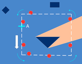
Fig. 16. The obstacles, the robot and its movement trajectories. A – robot starting and target position, the dashed white line – the robot’s trajectory, the red dots – robot’s location when the algorithm performed trajectory recalculation, the orange region – robot using only built-in odometry algorithms.
6. FUTURE WORK
The proposed algorithm and system conception can also be used with other sources of information about the robot’s location and obstacles, such as e.g. an external video system (similar to Distributed Computer Vision Systems Gardecki et al. (2016) and Radke (2010) but offering map data in a more convenient way). This would facilitate the detection of mobile obstacles, especially in areas with limited movement freedom. The structure of the proposed control system is designed in a modular way to enable the possibility to experiment with different conceptions and technologies.
It is also possible to extend the system’s capabilities by using more laser sensors to get more information. In this case, the limited-movement-area would be much smaller (Fig. 17).
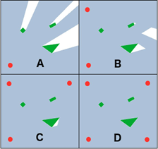
Fig. 17. Using more than one external stationary laser scanners for reducing limited visibility zones (visualization).
7. CONCLUSIONS
The proposed algorithm, although it does have limitations and imperfections, significantly increases reliability in identification of the robot’s safe-movement-zone. The algorithm significantly improves efficiency in tasks consisting in reaching a given location in comparison to standard, built-in algorithms. It can be extended with further laser sensors, cooperated with a vision system, or applied to other mobile robots.
Transferring some of the calculations to the external system instead of performing them on the robot, results in having the possibility to use a cost-effective environment for on-line computations. Such a solution is now increasingly popular in mobile robotics, especially if the robots are supposed to work under controlled conditions (e.g. in a specific location).
Table 2. Difference Between the Starting and Destination Point of the Robot (Trajectory – Fig. 16)
REFERENCES
- Gouaillier, V. Hugel, Blazevic, C. Kilner, J. Mon- ceaux, P. Lafourcade, B. Marnier, J. Serre, B. Maison- nier. Mechatronic design of NAO humanoid. In: 2009 IEEE International Conference on Robotics and Au- tomation, 2009.SoftBank Robotics, NAOqi Developer guide.
- Pot, J. Monceaux, R. Gelin, B. Maisonnier, Chore- graphe. Choregraphe: A Graphical Tool for Humanoid Robot Programming. Robot and Human Interactive Communication, IEEE,SoftBank Robotics, Laser head v.3.2.
- Gomez. Inside NAO, 2017.
- Gardecki and M. Podpora. Experience from the operation of the Pepper humanoid robots. Progress in Applied Electrical Engineering (PAEE), 2017Slamtec Co. Ltd., RPLIDAR A2 Laser RangeScanner.
- Wen, K.M. Othman, A.B. Rad, Y. Zhang, Y. Zhao. Indoor SLAM Using Laser and Camera with Closed- Loop Controller for NAO Humanoid Robot. Abstract and Applied Analysis, Hindawi, 2014.
- Wei, J. Xu, C. Wang, P. Wiggers and K. Hindriks. An Approach to Navigation for the Humanoid Robot Nao in Domestic Environments. TAROS 2013: Towards Autonomous Robotic Systems, pages 298–310, Springer, 2014.
- Gardecki and M. Podpora. Extending vision under- standing capabilities of NAO robot by connecting it to remote computational resource. Progress in Applied Electrical Engineering (PAEE), 2016.
- R.J. Radke. A Survey of Distributed Computer Vision Algorithms. Handbook of Ambient Intelligence and Smart Environments, Springer, 2010.
2405-8963 © 2018, IFAC (International Federation of Automatic Control) Hosting by Elsevier Ltd. All rights reserved. Peer review under responsibility of International Federation of Automatic Control. 10.1016/j.ifacol.2018.07.159
Ready to get started with your robot? click below to get get a free estimate, without any commitment"