Ilmi Mohd Ariffina,b*, Ahmad Ismat Hakam Mohamed Rasidia, Hanafiah Yussofa, Zulkifli Mohameda, Mohd Azfar Miskama, Adam Tan Mohd Amina, Abdul Rahman Omara
,aCenter for Humanoid Robots and Bio-sensing (HuRoBs), Faculty of Mechanical Engineering Universiti Teknologi MARA, 40450 Shah Alam, Selangor, Malaysia
bDepartment of Electrical Engineering, Politeknik Sultan Idris Shah, Sg.Lang, 45100 Sungai Air Tawar, Selangor.Malaysia
* Corresponding author. Tel.: +60 - 129776876 E-mail address: ilmi_ariffin@psis.edu.my
Abstract: This project presents a new approach of humanoid-operated 4-wheeled mobile platform. The robot used in this work is Nao by Aldebaran Robotics. Nao is chosen because of its versatility. Its wide range of movements allows it to perform various tasks such as steering through a simple programming algorithm. Arduino microcontroller target board is used to provide the interface between Nao robot and the mobile platform whilst humanoid robot NAO act as the main processing unit for the whole system. This project consists of several parts.
This paper focuses in the development of a sensing system, integration of Arduino microcontroller pro navigation with obstacle avoidance. Several tests has been done to determine the best initial setting to the overall system. The implementation of sensing system in the mobile platform shows very good result as the platform able to avoid obstacles while navigating.
Keywords: Navigation; Infrared sensor; Humanoid; Mobile Platform;
Nomenclature
 |
Turning angle of opposite front Tyre |
 |
Turning angle of incline front Tyre |
 |
Distance between both front Tyres |
 |
Distance between front shafts to front bumper |
 |
Distance between front and back shaft |
 |
Maximum sweeping radius |
 |
Minimum sweeping radius |
 |
Turning radius of 4-wheeled car |
1. Introduction
The development and research of self-autonomous mobile platform that able to navigate without human help has become the center of attention in the robotic field. The develop platform will opened many chances of use in variety of fields in providing services to the human beings such as providing guide or tour, mapping of an unknown environment, delivery, healthcare and defense without any human interactions [1] [4].
The aim in self-autonomous navigation mobile platform is usually to reach determined end point or goal of a certain coordinate in an environment starting from the certain start point in the environment. While it navigates, the mobile platform will enco unter different type of obstacles that will hinder direct navigation to the end point. These includes cluttered environment structure such as scattered static objects, wall and bumps that need to be avoided or moving on different terrains such as moving up through stairs, or performing some tasks before continuing the navigation [1], [5], [6].
To gain information from the environment for navigation, sensing system development is important. Getting the right information is vital to ensure correct obstacles avoidance in order to reach the goal point. Different devices have been used to collect the environment information such as laser range finder (LRF), infrared sensor (IR), Camera (vision sensor) and sonar [3],
[7] [10]. These devices usually paired with their own errors that need to be looked at and considered. There are also sensing systems that use more than one type of sensor combined [9].
The work involved in this research aim to develop a suitable 4 wheel mobile platform that can be used by NAO, to develop an algorithm that take data feed from both sensing methods and then execute a set of feedbacks (such as left turning) when the platform navigates. To measure the performance of the implemented sensing system in navigating without collisions, several experiments or tests is have been conducted to understand further any limitations of the developed mobile platform.
2. Mobile platform development

Figure 1 Mobile platform
Figure 1 show the developed 4 wheel mobile platform (a modified kid's remote control car for Humanoid robot NAO. Several parts of the mobile platform has been changed to suit humanoid robot NAO such as the steering wheel and additional motor was added to sustained NAO's weight of 7.0 kg. embedded micro-controller and sensor.
In this work, 3units of NODNA DF-SEN0164 Adjustable Infrared Sensor Switch are used to detect the front status of the mobile platform. The sensor is adjusted to sense any obstacle in the range of 50 cm from the sensor. The position of the embedded IR sensors in the mobile platform can be show in Figure 2(a) below, where the red circles mark the IR sensors.
To process the information received from IR sensors, Arduino Uno Micro-controller ATmega328 is used. The micro-controller is paired with a DC Motor Driver 2!15A to control the motor of the mobile platform. The micro-controller act as the controller unit of the mobile platform for both IR sensors and motor that act based on the command given by humanoid robot NAO. Interaction between the micro-controller and humanoid robot NAO occur using a serial link.
Two types of software are used to develop the mobile platform which is Arduino software for the microcontroller and Choreographe software for humanoid robot NAO. The main program however is run inside the Choreographe platform as NAO is used embedded central processing unit on the mobile platform. The interaction of this develop platform can be summarised in the figure 2 (b).
(a) (b)
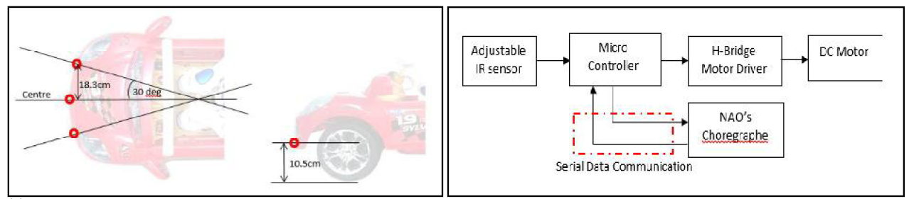
Figure2. (a) Infra-red sensor placement (b) System integration block diagram
3. Experiments
To determine the optima initial setting to the system, we perform several test which cover the response time of the system, simulated navigation routes versus actual routes taken, platform theoretical pose feedback versus actual pose feedback, and tests on performance of the sensing system.
3.1 System Response Time
For each of different types of conditions that will triggered the system to perform certain movement, poses or actions, there is a taken time for the system to return to its original condition. This means the system is finishing performing a certain loop and getting ready for another loop in the program flow. The time taken need to be recorded to know the response time of the system in order to know how well the develop platform react in an environment.
3.2 Turning Radius
The turning radius of the 4 wheeled mobile platform is tested under different left and right motor speed, M1 and M2. This is important to determine the navigation route taken by the mobile platform when avoiding an obstacle or determining the best set of motor speed for different radius of cornering.
The turning radius of the mobile platform at constant turning speed is approximated from the formula given in [11]. The mobile platform is assumed to have the same width between front and back tyres and the body shape is maximum to the outer tyre surface. The calculation using is neglected since both front tyres have the same angle to validate the equation.
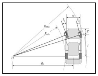
Figure 3.Turning radius calculation model
Where,
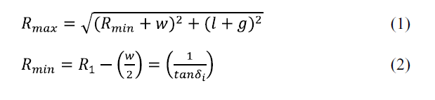
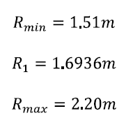
Using above mentioned equation, we calculate the related parameter for based on measured parameter of the mobile platform in Table 1.

Calculated value for:
3.3 Obstacle Avoidance
Adjustable infra-red sensor was used for obstacle detection. The detection range was set to 50mm. Each detection signal will be sent to NAO through serial communication with Arduino microcontroller. NAO will perform left or right maneuver based on detected obstacle position.
4. Experimental Result
Each experiment was conducted in controlled environment.
4.1 Response Time
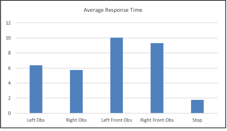
Based on the response time result in Graph 1, it is shown that the Left Front Obstacle and Right Front Obstacle achieve the longest time taken to complete their loops in the program which is around 9 seconds. This is probably due to the factor that reverse movement is imposed to their loop execution. Generally, the time taken to complete a single loop which involves movement of humanoid robot NAO is more than 5 seconds. This is not very good since in the mean time of 5 seconds, the mobile platform has navigated around 0.6 m in distance which is quiet large.
Some obstacles may already in front of the mobile platform which results in collision to occur. It is recommended that more improvement to be done to decrease the time taken for a single looping such as by decreasing humanoid NAO movement in turning the steering, or increase compatibility of develop navigation program.
Graph 1: Time taken for obstacle avoidance
4.2 Turning Radius
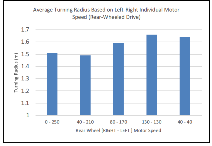
Graph 2: Average Turning Radius (Right Turn)
Graph 3: Average Turning Radius (Left Turn)
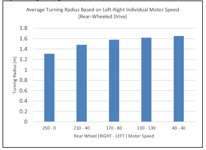
Based on Graph 2 and 3, it shows that to get shortest turning radius, one of the motor speed need to be set as STOP while the other one is at the highest speed. The smallest minimum turning radius recorded is around 1.3 m and the largest is around 1.6 m where both motor rotate at the same speed. Initially the standard platform only using single motor to drive and it is difficult to adjust the turning radius. After installing the additional motor, we able to perform turning radius control.
4.3 Obstacle Avoidance
Signal from infrared sensor sent to NAO through Arduino and serial communication protocol to allow NAO to navigate the mobile platform away from the detected obstacle. Figure 4 below showed the experimental setup and result of the navigation
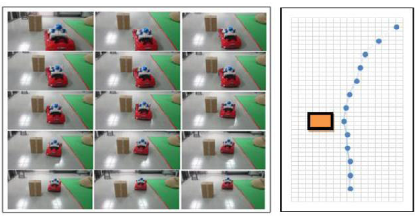
Figure 4. Obstacle avoidance sequence (left) and actual trail navigation (right)
5. Conclusion and Future Work
This paper proposed new humanoid navigation using mobile platform. In our system, we integrated the infrared sensor and humanoid robot NAO to realize the navigation with obstacle avoidance ability. Preliminary result showed that the system can be tuned to get good performance. However, the detection using infrared sensor is not enough as detection area is limited to one straight line detection. The usage of laser range sensor can be considered in the future to provide better detection.
Acknowledgement
The authors gratefully acknowledge the Ministry of Education Malaysia (MOE) for the fund received through the Exploratory Research Grant Scheme (ERGS), [Project file: 600-RMI/ERGS 5/3 (15/2013)] and Niche Research Grant Scheme (NRGS), [Prohect file: 600-RMI/NRGS 5/3 (1/2013) and 600-RMI/NRGS 5/3 (2/2013)], COE of Humanoid Robot and Bio-Sensing (HuRoBs), Politeknik Sultan Idris Shah and Universiti Teknologi MARA (UiTM) Shah Alam, Selangor for their support.
References
- [1] Midwest Symp. Circuits
- Syst., pp. 562 565, 2012.
- [2] 13th IEEE-RAS
- International Conference on Humanoids Robots (Humanoids), 2013, vol. 2013.
- [3] H. D. Eom and J. - IEEE International Conference on Software Engineering, 2014, pp. 2 3.
- [4] IEEE Int. Conf. Electro Inf.
- Technol., 2013.
- [5] IEEE International Conference
- on Intelligent Robots and Systems, 2011, pp. 4844 4849.
- [6] IEEE Int.
- Conf. Intell. Robot. Syst., pp. 2658 2664, 2013.
- Robot. Syst. 2006 IEEE/RSJ, pp. 814 819, 2006.
- And Mapping with
- Mobile Object Tracki Comput. Inf. Sci., 2009.
- 3rd Int. Conf. Inf. Fusion, FUSION 2000, vol. 2, pp. 18 25, 2000.
- 12th International Conference on Control,
- Automation and Systems (ICCAS), 2012, 2012, pp. 459 461.
- J. Sci. Eng. Res., vol. 4, no. 12, pp. 2177
- 2184, 2013.
© 2015 The Authors. Published by Elsevier B.V. This is an open access article under the CC BY-NC-ND license (http://creativecommons.org/licenses/by-nc-nd/4.0/). Peer-review under responsibility of organizing committee of the 2015 IEEE International Symposium on Robotics and Intelligent Sensors (IRIS 2015)
Ready to get started with your robot? click below to get get a free estimate, without any commitment"


 Too much to read? Don't have time?

.webp?width=124&height=124&name=image%20(1).webp)
.webp?width=169&height=87&name=image%20(2).webp)